Description
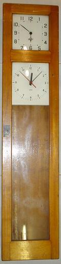
At first sight, the Gents’ (of Leicester) Pul-syn-etic clock looks like a short case wall mounted pendulum clock. It is only when you realise that there are no weights and you hear it in operation that you discover that this is something rather different.
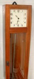
Officially called a C7 transmitter, the case is a very elegant but unadorned hardwood box with a glass front, about 1.3m tall, 30cm wide and 20 deep reminicent of laboratory instruments. Most examples have a square deco style white face with a simple straight minute hand and ring hour hand. This is mounted in the door at the top above the glass.
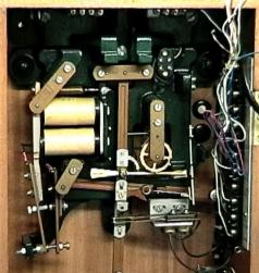
Opening the door will reveal a nearly free swinging pendulum (A) adjusted to 1 second per half cycle. Watching the clock operate for a few minutes will reveal its operation. Refering to the diagram below, the pendulum moves a follower (B) which trips an escapement wheel (C) once every cycle. The wheel is fifteen teeth (thirty seconds) around and at one point there is a deep notch. This causes the actuator to slightly move upwards on the next right swing so that it fouls a vertical spring latch (D) on the right hand side.
You now need to watch carefully because everything happens quickly. The latch releases a bar (E) which contains a small roller. This rests on the pendulum follower and as it swings to the left it rolls off the edge and down the side. This side piece (F) is angled so that the weight of the roller and impulse-bar mechanism gives the pendulum a slight nudge to keep it swinging. So far this has all been mechanical, however when the roller reaches the bottom (when the pendulum is roughly in mid swing,) an electrical contact is made at the lower left of the impulse-bar (G). This enables a current to flow around the circuit which includes a large double coil solenoid (H) at the left. The solenoid pulls a long bar (J) towards itself which shoves the impulse-bar back to re-engage into its latch before the pendulum can swing back again. In the process it disconnects the current so that the solenoid-bar falls back again. This is what creates the loud “clunk” every thirty seconds.
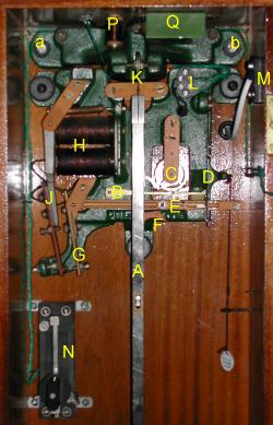
The current which re-engages the latch also flows to slave
mechanisms, one of which is the dial on the front. These get
the same pulse every thirty seconds to move the hands half a
minute at a time using a solenoid operated ratchet. It is this
feature that gives the clock its name and makes it a master
clock (or transmitter as the manufacturers call it). It is
possible to have many slave dials in series (I don’t know
of any limit) and this made the clock popular in schools,
factories, offices and other public buildings. My one came from
the Llandudno Hotel in North Wales. It was possible to get a
variety of standard slave dials or the bare mechanisms could be
obtained for architect designed clocks. There is a fine example
in the library at ![]() St. Hugh’s College in Oxford.
Special mechanisms were also available to drive time recorders
for factories, turret clocks for the outside of buildings (see
also St. Hugh’s and Chris Bolwell’s site) and bell
actuators for schools.
St. Hugh’s College in Oxford.
Special mechanisms were also available to drive time recorders
for factories, turret clocks for the outside of buildings (see
also St. Hugh’s and Chris Bolwell’s site) and bell
actuators for schools.
There is a pull string on the right that, when operated, causes the follower to release the latch on every swing of the pendulum. This is to advance the clock for Daylight Saving Time. It takes four minutes to advance one hour. In the autumn, the easiest method is to stop the clock for the hour.
Construction
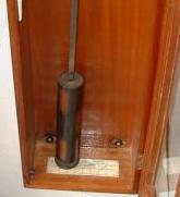
The pendulum rod is flat invar steel with a threaded extension welded to the bottom. The bob is a cylindrical bronzed steel can 254mm (10") long by 57mm diameter (2 ¼") diameter, perhaps containing large lead washers weighing a total of approximately 4.9Kg. The bob is a close but free fit to the rod and a cast metal circular disk at the bottom allows up and down adjustment on the threaded part of the rod. The whole is suspended by a strip of spring steel clamped to the rod and also to a pivot (K) which allows a small amount of front to back movement. On the bottom of the case is a graduated swing scale which serves very little purpose except to show that the case is vertical. The mechanism (including the pendulum pivot) is all mounted on a very substantial cast iron frame, usually painted green, and this projects out of the back of the case to provide the main wall attachment point above the case.
The moving mechanism parts are all bronze painted and are probably mild steel except the escapement wheel and pendulum follower which are of clock brass. The latter has a steel pin which goes through a slot in the pendulum rod (just below A). In addition to the mechanical parts, there are a few electrical components which vary from model to model. They all have a large two coil solenoid (H) at the right and some terminal posts on the left. Mine has two sets, one for the front face slave (L) mounted on the frame, and one for the power supply and external slaves (M) screwed to the wooden case. Below the main frame on the left is a wire-wound rheostat (variable resistor, N) to adjust the current allowing for different numbers of slaves and a compartment to hold the instruction book. Mine also has some additional components above the frame which are a choke (inductance, P) and condenser (capacitor, Q) in series together and, I think wired across the contact points. This will be to suppress arcing. Other examples have the rheostat and suppressor mounted in different places as they are just screwed to the wood. The wiring is green covered stranded wire, twisted in pairs or more, and routed mostly above and behind the frame. It looks more modern than the rest of the clock, but I have no evidence that it has been rewired.
Setting up
Choosing a place to install this clock should be done with care. It is rather noisy in operation and I can hear ours two floors away, though at that distance it is not annoying (it is an alternative to counting sheep if you can’t sleep!) It needs a substantial masonry or brick wall which doesn’t flex. Partition walls are not suitable and, in any case, will transmit the noise all around the building. It is probably best not to place it too close to a heat source as changes of temperature will disturb the timekeeping. That said, it is quite elegant and a conversation piece, so an entrance hallway is ideal. You will also need to consider access to a power point, depending on what power option you are choosing (see below).
The primary requirement for setting up this clock is a) to take the very substantial weight in a way that is absolutely rigid. It must not move with the swing of the pendulum else the time keeping will be impaired. And b), it must be vertical. To assist this, there are small inlaid brass studs in the front of the case, top and bottom, behind the door and on the left hand outside. These can be used with a plumb line for lateral and front to back alignment. There is an extra wood panel at the top and bottom rear which stands the case away from the wall by about 1cm. This can be useful to span small dado rails and allow for uneven walls.
First, carefully remove the pendulum from its hanger making sure not to bend the follower bar (which can be rather a tight fit).
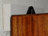
It was getting the case vertical which made life hard for me. I positioned it against the wall and, at the last minute, discovered that the top was tipped back by 3cm relative to the bottom. So, as you will see from the pictures, I had to install a mounting block to the wall before attaching the clock. In fact I slightly over did it and it now leans out a fraction, but it tolerates a little error.
The main support is a large hole in the cast iron frame
above the case. This should be hung on a substantial screw or
![]() Rawlbolt plugged into the masonry behind.
Because of the extra padding on mine, I used a 3" (8cm) coach
screw through the mounting block and into the wall behind. The
screw needs to protrude by about a centimetre to hang the
bracket, so a large diameter shank is required to avoid
bending. The coach screw I used was 9mm in diameter and had a
square head for use with a spanner. I had to file the corners
off the head a little to get it through the mounting hole on
the clock.
Rawlbolt plugged into the masonry behind.
Because of the extra padding on mine, I used a 3" (8cm) coach
screw through the mounting block and into the wall behind. The
screw needs to protrude by about a centimetre to hang the
bracket, so a large diameter shank is required to avoid
bending. The coach screw I used was 9mm in diameter and had a
square head for use with a spanner. I had to file the corners
off the head a little to get it through the mounting hole on
the clock.
Once the clock is hung the final alignment can be done. If possible I would suggest putting some damping material behind the top and bottom to absorb some of the vibration. A thick soft type mouse mat cut in half provides two very suitable pieces. There are four further screw holes which now need to be used. At the bottom of the case are two slots in the wood which, I am told, originally had rubber bushes. Mark the wall behind at the centre of these slots and drill and plug them for ordinary (long) wood screws. At the top on both sides of the frame are two holes right through the cast iron (a and b on the diagram above). Mark, drill and plug these as well. Be sure to get the case precisely lined up for these as there is only a little adjustment.
Now the clock can be hung in it’s final position. Hook the case over the main support point and loosely insert the lower two case screws. I found that large bath tap washers were an ideal way to buffer these screws from the case. Tighten the top screw so that there is no gap but a little movement is possible for adjustment and get the case as vertical as possible. Now re-hang the pendulum (the shiny side of the rod should face the front), carefully hooking the slot over the follower pin and make sure that the hanger is bedded down into the frame. It is a good idea, at this stage, to make sure that the adjustment screw disk at the bottom of the pendulum is free. Turn it back and forth a few times and apply a smear of grease to the thread, but don’t move it too far away from its original position otherwise it will be hard to put right later. The final adjustments side-to-side can now be made to get the pendulum hanging in the centre of the scale. Tighten the lower screws and insert the two remaining upper screws (also with tap washers) and tighten them down. The clock should now be rigid on the wall and unable to be moved by a (reasonable) shove sideways. It is possible to adjust the pendulum sideways on its hanger, but this should not be necessary.
Wiring
The instruction book says that the mechanism needs 0.22 Amp to operate. I have found that it will function on a little less than this. The slave movement coil is about 4 Ohms and the master solenoid is about 29 Ohms. The rheostat (on mine) allows adjustment from 0 to 115 Ohms. The simple mathematics from Ohm’s law says that V = I R i.e. 0.22 x 33 (for the one internal slave) requires 7.26V.
There are a number of ways that this power can be provided. Originally this was either dry cells (zinc-carbon) at 1.5V each in series, lead-acid accumulators at a nominal 2V each in series or a transformer and rectifier from what they called the “service main.” Large capacity dry cells are now virtually unobtainable. I remember my school used cells that were 30cm high and 8cm square which lasted about three years and they had a small cupboard full of them, all wired in series. The mains-transformer option has the disadvantage that if the current fails, then the clock stops. Although unexpected, the second option of accumulators is still a viable option. Small sealed lead-acid batteries (with the acid as a gel) are readily available and a matching trickle charger can be wired to keep them topped up.
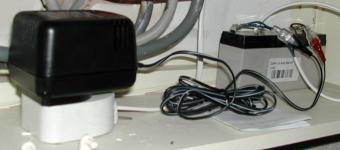
I bought a 6V set (![]() Maplin part numbers
Maplin part numbers YJ68Y 2.8Ah
now discontinued and LJ92A) before realising that a
12V set would have been better, but it still works with the
rheostat set to zero. I think this will run for at least 3
weeks without the charger connected. You will need to check
that the charger suits the battery you have chosen, but there
is quite a wide range available (I would now suggest
Maplin part numbers MM23A 12V 2.2Ah or XG75S 2.8Ah and charger
LL30H.) The actual voltage per cell is nearer 2.2V which
is why mine works with the smaller battery. The battery comes
with Lucar connectors as does the charger, so you need to make
up some leads with insulated connectors that allow both to be
connected in parallel. The battery is delivered discharged so
put it on charge overnight before testing. If you are using the
direct transformer option, make sure that it gives DC at 9 to
12V under load and capable of supplying 250mA. If you are
planning to run multiple slaves then 12V will run at least 5
additional dials. Any more than that and you are on your own.
Something I didn’t do, but certainly would if running
remote slaves, is to insert a fuse in the supply lead. The
current potential for lead-acid batteries in the case of a
short circuit is very high and creates a fire risk. A household
1A cartridge fuse in holder would be ideal.
Attach the power supply to the two main terminals (M) on the right hand side—the polarity +/- doesn't matter. There is a hole in the back of the case to run the wires or it would be possible to install the battery inside the case with a little ingenuity. Undo the screw in the knob and adjust the rheostat (N) to maximum resistance (the top on mine). Attach an ammeter to the two terminals half way up the solenoid arm (about at position J), one to the solenoid-arm itself and one to the impulse-bar. This requires two people really—adjust the rheostat until the meter registers 0.22A. Beware:—the solenoid will jump when sufficient current flows and may dislodge the ammeter probes but no harm is done, just re-connect them. Now re-tighten the rheostat locking screw. A significant feature of this clock is that no power is consumed when it is stopped. There is no need to disconnect the power.
Adjusting
Swing the pendulum by hand gently from side to side and make sure that the follower-bar (B) goes through the hole in the latch (D) cleanly. It is supposed to be in the middle but mine sits well forward, possibly because the follower mechanism is slightly bent. The main reason this happens is that the pin on the follower is a tight fit in the pendulum rod and when removing the pendulum, it is very easy to pull the follower as well. If it fowls the latch hole then it will need to be gently bent by pushing (or pulling) on the main follower bar behind the pendulum. Once this is clear you can set the pendulum swinging and after a few seconds the mechanism should operate and all will be well. If the impulse bar does not re-engage in the latch then the current is in-sufficient. If nothing happens at all then check that all the terminal screws are tightened down. A continuous series circuit is required between battery, contacts, solenoid and slave, though tracing the twisted wires (all of the same colour) is quite tricky.
You now need to put the clock roughly right. Differences of more than an hour forward (or any time backwards) are best adjusted by stopping and starting the clock at the appropriate times. I had to move mine by six hours, so I ran it until it showed 7 o’clock, then stopped it until a bit after 7 the following evening when I started it again. Finally adjust it a few minutes using the “advance” string. I have found that this mechanism always advances the clock by one more pulse than you expect it to, but if you overshoot then you can always stop the pendulum for a short period and try again.
Depending on how accurate you want to get it, you now need a reference clock or the radio time signal. I used a radio synchronised wall clock with a sweep second hand—this is where the loud clunk every thirty seconds became useful because I could hear it from the other end of the house. Get the clunk to occur as near to the minute/half minute as you can by stopping the pendulum for the few seconds required. Now measure how many seconds before or after the half minute the clunk occurs. Write this down and do the same about 24 hours later. The difference will tell you how fast or slow the clock is running. Also check that the minute hand is still right in case you are more than 30 second per day wrong! The clock can be made to run faster by turning the adjustment wheel to the right or slower to the left. The book says that it is one notch on the wheel to adjust it by one second per day but there was quite a bit of hysteresis on mine, particularly to the left. Repeatedly take new timings roughly 24 hours apart and within a week I got mine to better than one second a day.
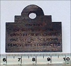
The instruction book talks about a weight supplied that could be placed on top of the pendulum to speed it up, or on the adjustment ring below to slow it down, by one second per hour in each case. This could be used to make small adjustments to the clock whilst still maintaining a monotonic increasing time function (albeit with 30 second step changes). There should be a hook supplied inside the case to hang the weight (usually just below the instruction book) when it is not in use. Both the weight and hook were missing from mine. Tony Daniels kindly sent me a photo of his. It weighs 28 grams (1 ounce) and is inscribed
FRONT For correcting Pul-Syn-Etic Transmitter Pendulum
REAR On top of bob will gain On bottom will lose One second per hour Remove when Corrected

The same technique can be used with much smaller weights for fine tuning and I have recently been shown a picture of some “Regulating Weights” for this purpose. I have made a set of my own in ¼ g. increments for this purpose, using garden wire.
Other clocks
[I have not been able to trace some of the following pictures to their owners so if I have stolen yours, please let me know and may I have your permission please. If not I will remove it as soon as possible.]
Searching on the internet and from clock dealers catalogues, I have discovered that there were different models of this clock made. Mine is numbered #7117 (on a disk on the key ring, and also stamped into the wood at the top and/or bottom of the case next to the brass alignment studs—thanks John), and was probably made in the late 1930’s or early 1940’s. #5615, #5820 & #9541 are the same design as is #6776, but in this case, the slave dial has been removed (or never fitted). These were probably made up to at least 1955. I have seen one (serial 7273) which has been rebadged to "BLICK - ELECTRIC".
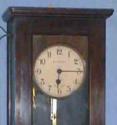
The early ones, certainly up to 1936 had an oak (#3419) or mahogany (number #4001 at St. Hugh’s Oxford 26 Mar 1936) case and round dial. These are different but close numbers so it is possible that the mechanisms were supplied without cases to to be fitted to suit the customer. They were certainly made to order, though in standardised cases, until quite late in their production, which is why there is quite a bit of variation. The one owned by Alistair Ruddle, which is of this type and #2658, is dated 4 Jan 1928. Tony Daniels’ also has the round (but silvered) face and is #4560.
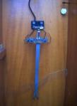
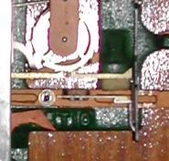
I discovered one (#8533) on ![]() e-bay
which seemed to have a separate pendulum follower with a
mercury switch. This is about 10cm below the main follower
(picture to right) and may have been a similar mechanism to
another one I discovered at a dealer’s (
e-bay
which seemed to have a separate pendulum follower with a
mercury switch. This is about 10cm below the main follower
(picture to right) and may have been a similar mechanism to
another one I discovered at a dealer’s (![]() Old
Father Time Clock Centre, picture in chapter above) that
had another slave dial with a sweep second hand behind the
glass at the top of the case. The mercury relay may have been
to provide a 1 second pulse to drive this second dial.
Old
Father Time Clock Centre, picture in chapter above) that
had another slave dial with a sweep second hand behind the
glass at the top of the case. The mercury relay may have been
to provide a 1 second pulse to drive this second dial.
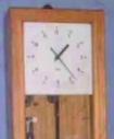
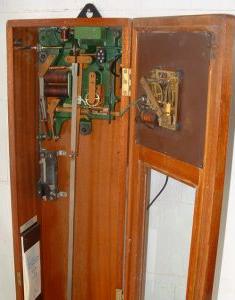
A very late design (at least 1961) on clock #13735 introduced a round marking on the square dial and no wooden crossbar. Clock #14958 had the same face and is dated 22-7-74. Clock #14836 is similar but the dial has been extended down to provide space for an extra slave movement, possibly for a bell actuator, strike or similar purpose (pictures to the left). All of these used the same standard mechanism. Finally, I came across one with a basically standard mechanism but with a lot of extra switching and connectors. This may be an alternative “second hand” pulse mechanism or something more complex.
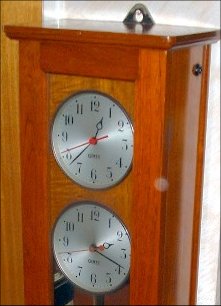
Tony Daniels’ clock (#4560) has a special feature—a second dial below the first which is driven from a mains synchronous movement. This was used in an elctricity substation as a frequency drift control and was used to correct overnight error during the daytime by adjusting the mains supply frequency. This was necessary because many people had synchronous clocks and the authority were obliged to be accurate over the long term. The reference clock was also made by Gent and is a precision movement. [The picture suggests that one or both were not running when it was taken.] #3662 14 Aug 1934 is similar and is currently undergoing restoration in the Netherlands. The owner has obtained a copy of the “Operating and Maintenance Instructions for Standard and Frequency Time Equipment” [158K] from another source in New Zealand.
There were other clocks made with a mechanism that operated in a similar way to the Gent. For example the Post Office type 36 which was used to time telephone call charges in local exchanges used a Magneta movement which, I think, was magnetically impulsed. A type that I am particularly interested in locating is one that was on the wall of the physics laboratory in my secondary school (Ravensbourne School in Bromley, Kent, formerly Bromley Grammar School for Boys.) I was told at the time (1971) that it was assembled from a kit by the then head of physics, Mr. G. Pullham. The design was similar to the Gent but, I think, had a shorter 1 or 1½ second pendulum and with a “grid-iron” type compensated bob. It was also a lot quieter in operation, not interfering with lessons.
Addendum
One of the interesting variations to the Pul-syn-etic clock was a mechanism to allow it to be regulated by an external time source. The mechanism exploited the readily available telegraph system used extensively on the railways. How it worked was that at regular intervals, I think on the hour, a pulse was sent by telegraph from somewhere authoritative like the Greenwich time standard. If this signal arrived before the 30 second impulse the clock was running slow so a small weight was lowered onto a tray attached to the pendulum causing it to run slightly faster. If it arrived after the impulse, the clock was running fast so the weight was lifted from the tray causing the pendulum to run slightly slower. The clock by itself was regulated to run a very small fraction slow. So what this did was to cause the time keeping to oscillate between very slightly fast and similarly slow. Note: to understand this you need to realise that adding extra weight to the pendulum near the fulcrum very slightly raised the centre of gravity and hence very slightly increased the frequency above the normal 0.5Hz. The net effect was to compensate the time from variations due to temperature and other local interference.
Inspired by this I wanted to do something similar using internet time as the reference time source. I had many years experience using internet time to regulate the clocks on the network of a major manufacturer. I also felt that it should be possible to go a little bit better and, rather than oscillate the time either side of true I could adjust the actual pendulum frequency to much nearer true than was possible using the manual mechanism whilst also following local temperature changes. My thought was to still use the tray attached to the pendulum rod quite near the top but to progressively load it using a fine chain until the beat was perfect. I had also got interested in the recently available Raspberry Pi miniature computer which had the facility to read external events and act upon them under program control.
There were a number of snags to overcome. Firstly I had to discover exactly when impulses occurred and how far apart in time they were. They should be at 30 second intervals but I discovered that there was a limit to the resolution of the clock available in the Pi. What I found I had to do was take repeated readings over a long interval and average them. Obtaining the impulse was the next problem. My knowledge of electronics was modest and I took advice from a friend who advised that monitoring the noisy high current impulse from the clock was best done using an opto-isolator to keep it well clear of the sensitive electronics in the Pi interface. The last hurdle was something I understood much better and that was writing the software to control it all which turned out to be much harder than I expected.
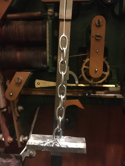

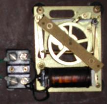
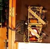
These two pictures show the mechanism for raising and lowering the chain onto the tray. I discovered that the chain required to make a significant difference was not as fine as I thought it would be and this is what would best be described as lavatory chain. The tray is made from an old aluminium cooking tray of the disposable sort sold for Christmas turkeys. It is cut and folded then stuck together with superglue with a tab extension top and bottom attached to the pendulum rod using electrical tape. The cord is heavy duty sewing thread which is run over a large smooth hook screwed into the case woodwork. On the far left I have mounted a stepper motor in a cage made from folded perforated metal secured with pop rivets. The cord makes a number of turns around the pulley and the software has the ability to count the steps so knows exactly where the chain is at any time. The red and black wires that are in the picture are the sense wires attached to convenient terminals on the condenser, Q, described above.

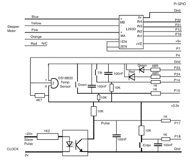
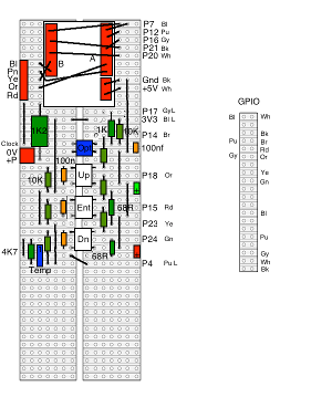
My rather crude external circuitry is contained on a piece of strip board and is dominated by a purchased stepper motor driver at the top. Below are a number of separate circuits including the sensor at the top, three control buttons down the middle used to initialise the maximum travel of the chain and two indicator LEDs on the right. At the bottom left is a temperature sensor that is only used for reporting as I found it difficult to correlate with the required adjustments. This is all connected to the Pi GPIO using a ribbon cable. Below this is the Raspberry Pi itself mounted in a Lego box and crudely taped to it is a small LCD display added as an afterthought so I could report what was going on. As you can see from the schematic there is nothing complex in the electronics.
The displays show in sequence at five second intervals as shown below (sorry that they are a bit hard to read). The first is an introduction and shows the date but the number at the far right shows the progress through the initialisation sequence. The second shows the current accuracy relative to the internet time. The "Datum" is the time when the time keeping was last checked and is currently set as every half hour. The third shows the accuracy of the pulse relative to thirty seconds. The fourth shows the absolute position of the weight chain in units of stepper motor increments. The fifth shows the temperature inside the case. The latter gave a bit of a surprise. First I was disappointed at how poor the accuracy was compared to a laboratory mercury standard. I had to compensate in the software both an offset and factor. And secondly that the temperature drifted so rapidly. I was expecting it to be reasonably stable inside the case but in fact it moves around with the temperature of the house quite quickly. As a consequence less adjustment is required in the summer than the winter when the central heating comes in twice a day. The clock is a bit too close to a radiator!


The software that drives this, written in Python, is available on application with no guarantees
Some good links.
![]() A History of Horology—with mention of electric clock development.
A History of Horology—with mention of electric clock development.
![]() PULSYNETIC—The best of the lot, and some very
special clocks.
PULSYNETIC—The best of the lot, and some very
special clocks.
![]() A video of a Pul-Syn-Etic clock in action—though there
are strange noises off that have nothing to do with it. Others are available on You-Tube
A video of a Pul-Syn-Etic clock in action—though there
are strange noises off that have nothing to do with it. Others are available on You-Tube
![]() Electric Clocks—A good description
of how this and other electric clocks work by Michel Viredaz
(translated from French)
Electric Clocks—A good description
of how this and other electric clocks work by Michel Viredaz
(translated from French)
![]() Electrical horology systems—[LINK BROKEN 2016] A
similar page by Werner Moser (translated from German)
Electrical horology systems—[LINK BROKEN 2016] A
similar page by Werner Moser (translated from German)
![]() Martin Ridout’s Electrical Horology
pages
Martin Ridout’s Electrical Horology
pages
![]() Barrie’s Virtual Museum of
Clocks. [LINK BROKEN 2014]
Barrie’s Virtual Museum of
Clocks. [LINK BROKEN 2014]
![]() Old Father Time Clock Centre—A
shop in London.
Old Father Time Clock Centre—A
shop in London.
![]() Bush House Control Room—[LINK BROKEN 2016] Gent
clocks in use at the BBC.
Bush House Control Room—[LINK BROKEN 2016] Gent
clocks in use at the BBC.
![]() Synchronome—[LINK BROKEN] A shop in Brixham,
Devon.
Synchronome—[LINK BROKEN] A shop in Brixham,
Devon.
![]() Layman’s Guide to the Gent’s
Pulsynetic Waiting Train Electrically Driven Pendulum Turret
Clock—Chris Bolwell’s excellent description of
a refurbishment project. An insight into how Gent master clocks
were used to drive outdoor turret and tower clocks..
Layman’s Guide to the Gent’s
Pulsynetic Waiting Train Electrically Driven Pendulum Turret
Clock—Chris Bolwell’s excellent description of
a refurbishment project. An insight into how Gent master clocks
were used to drive outdoor turret and tower clocks..
The ![]() Electrical Horology Group of the Antiquarian Horological Society.
Electrical Horology Group of the Antiquarian Horological Society.
![]() Electric Masters—a good introductory site with some excellent pictures.
Electric Masters—a good introductory site with some excellent pictures.
 Webmaster
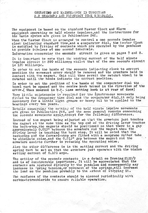